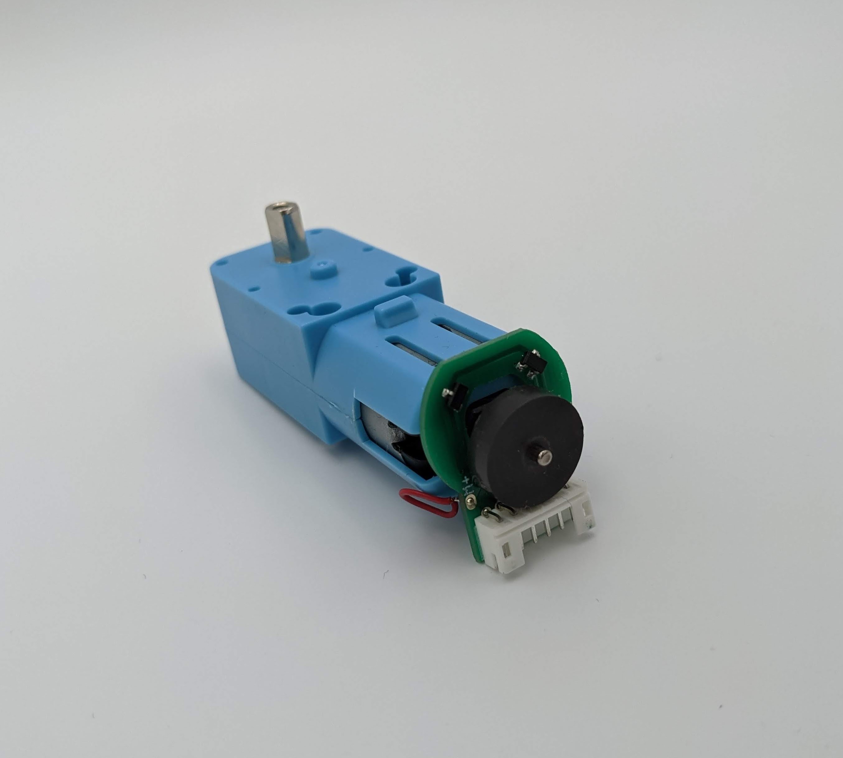
Motor and Encoder
Motor with Wheel Encoder
The DG01D-E is a single hobby motor with a hall speed encoder. This motor requires a voltage between 3-9V, has a gearbox ratio of 1:48 and a speed of 90RPM at 4.5V. The voltage between positive and negative is determined according to the power supply voltage of the single chip microcomputer used, generally 3.3V or 5V is used.
The hall sensor can sense the North and South poles of its magnetic plate. When the hall sensor senses the South of the magnetic plate, the hall output will result in a high level. Meanwhile the North is the inverse and, when sensed, the hall output will result a low level.
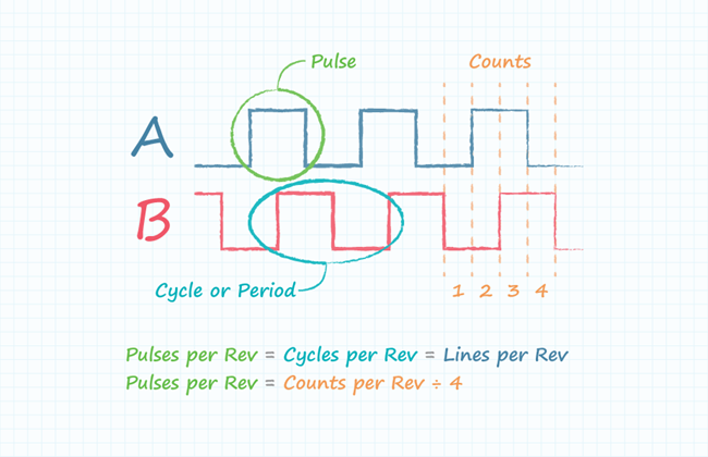
It is not clear which encoder the current DG01D-E motor has built in. To find its resolution (counts, cycles and pulses per revolution, see image below for the difference), we can spin the wheel for one full rotation and record the number of ticks, also known as counts. This way we can obtain the geared resolution, meaning the resolution measured at the wheel axle and not the motor shaft. It is possible to calculate the resolution at the motor shaft from the resolution measured at the wheel axle when we know the gear reduction ratio. Because the datasheet is not precise about the gearbox ratio (1:48) it is hard to know exactly the pulses, counts, (and cycles) per revolution at the motor shaft itself (where the encoder is attached). The output resolution of the wheel (after the gear reduction) on the other hand can be measured quite easily with a script encoders_test.ino code. From these measurements it seems that this encoder has only 3 pulses per revolution (ppr) because with the code that reads both edges (rising and falling) of both channels we can observe roughly 542 at the wheel output shaft (lets round it up to 576 counts per wheel revolution to obtain 3 ppr. We could also assume that the gear ratio might not be exactly correct). So 576 counts / 48:1 gear ratio / 2 channels / 2 edges = 3 pulses per revolution at the motor shaft. Having an encoder with higher ppr (and having the same gear reduction ratio of 48:1) would yield a more accurate odometry. For example let's say we get an encoder with 7 ppr, then we get the following output resolution at the wheel: 7 ppr (at motor shaft) * 48:1 gear ratio * 2 channels * 2 edges = 1344 ppr (measured at wheel). The following image shows the difference between counts, pulses (and cycles).
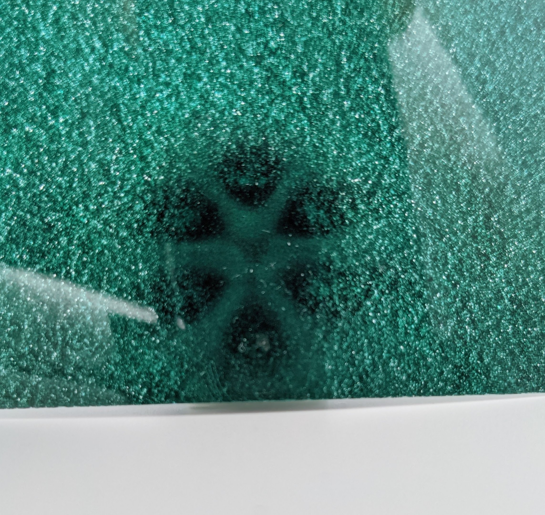
It is also possible to get the PPR from the number of magnetic polse, which you can see with a magnetic field paper:
There are six poles which results in three pulses per revolution.
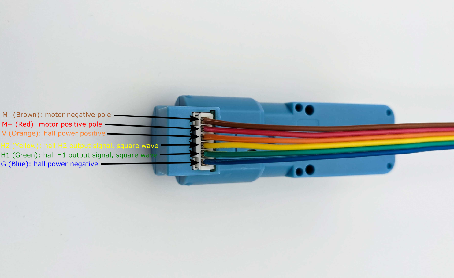
Terminal Pin Layout
The pins on the product are as follows, when looking at the connector on the housing, motor down/connector up, from right to left. The colors correspond to the included cable when plugged in to the connection slot.
- G (Blue): hall power negative
- H1 (Green): hall H1 output signal, square wave
- H2 (Yellow): hall H2 output signal, square wave
- V (Orange): hall power positive
- M+ (Red): motor positive pole
- M- (Brown): motor negative pole
The following image shows the motor from its side with the corresponding pin descriptions:
Wheel Encoder Setup with ROS
The following video gives an idea of what has to be done to get the motor and encoder working with ROS.
Wheel Encoder Measurements
This section shows oscilloscope waveform measurements of the quadrature encoder in the DG01D-E motor.
The motor is connected to the Grove I2C Motor Driver that is powerd with 10 VDC.
The motor_example.py applies 50-100% of the 10 VDC which leads to the following output voltages on the motor:
Voltage sweep measurements
- 0:00 Forward Speed 50: 6.5 VDC
- 0:12 Back Speed 50: 6.5 VDC
- 0:23 Forward Speed 60: 6.9 VDC
- 0:34 Back Speed 60: 6.9 VDC
- 0:46 Forward Speed 70: 7.2 VDC
- 0:56 Back Speed 70: 7.2 VDC
- 1:07 Forward 80: 7.3 VDC
- 1:18 Back 80: 7.3 VDC
- 1:29 Forward 90: 7.6 VDC
- 1:41 Back 90: 7.6 VDC
- 1:52 Forward 100: 7.9 VDC
- 2:02 Back 100: 7.9 VDC
At the bottom of the pico scope window the cycle time, duty cycle, high and low pulse width measurements are shown for both encoder signals. Oscilloscope is the PicoScope 3000 Series with 2 Channels. To download and install Pico Scope software on Linux refer to the documentation.
Summary of installation instructions
- Add repository to the updater
1sudo bash -c 'echo "deb https://labs.picotech.com/debian/ picoscope main" >/etc/apt/sources.list.d/picoscope.list' - Import public key
1wget -O - https://labs.picotech.com/debian/dists/picoscope/Release.gpg.key | sudo apt-key add - -
Update package manager cache
1sudo apt-get update -
Install PicoScope
1 | |